Diagram / Infographic
USB-C Cable Exploded Assembly Infographic
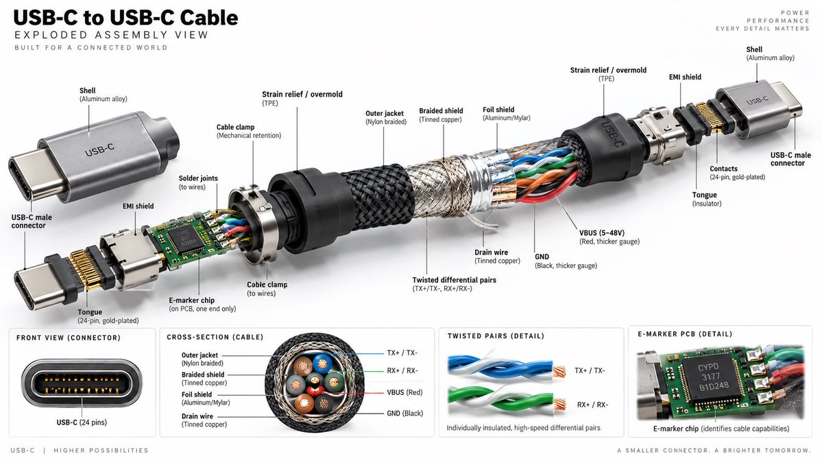
Create a hyper-realistic, high-resolution technical exploded assembly view of a USB-C to USB-C cable against a clean white background. The image should be wide format (16:9) and resemble a premium product infographic.
Full prompt
Create a hyper-realistic, high-resolution technical exploded assembly view of a USB-C to USB-C cable against a clean white background. The image should be wide format (16:9) and resemble a premium product infographic.
**Layout & Structure:**
- **Header:** Top left text reads "USB-C to USB-C Cable" in large bold black font, followed by "EXPLODED ASSEMBLY VIEW" and smaller text "BUILT FOR A CONNECTED WORLD". Top right has faint grey text: "POWER PERFORMANCE EVERY DETAIL MATTERS".
- **Main Visual:** A central horizontal exploded diagram showing the internal components of the cable separated from left to right.
- **Bottom Panels:** Four distinct rectangular detail boxes along the bottom edge.
**Exploded View Details (Left to Right):**
1. **Left Connector Assembly:** A silver aluminum shell labeled "Shell (Aluminum alloy)" with "USB-C" engraved on it. Below it, a separate connector head labeled "USB-C male connector". Internal parts include a green PCB with an "E-marker chip", gold pins labeled "Tongue (24-pin, gold-plated)", and a metal shield labeled "EMI shield".
2. **Strain Relief:** A black rubber cone labeled "Strain relief / overmold (TPE)".
3. **Cable Layers (Center):** The cable is peeled back to reveal layers:
- Outer layer: Black woven texture labeled "Outer jacket (Nylon braided)".
- Middle layer: Silver mesh labeled "Braided shield (Tinned copper)".
- Inner layer: Foil labeled "Foil shield (Aluminum/Mylar)".
- Core wires: Visible twisted pairs of blue, orange, green, and red wires. Labels point to "Twisted differential pairs (TX+/TX-, RX+/RX-)", "VBUS (5-48V) (Red, thicker gauge)", "GND (Black, thicker gauge)", and "Drain wire (Tinned copper)".
4. **Right Connector Assembly:** Mirrors the left side but without the PCB/chip visible inside the immediate neck. Shows the metal shell, strain relief, and connector tongue.
**Bottom Detail Panels (Left to Right):**
1. **Front View:** A close-up of the oval connector port showing the 24 pins. Label: "FRONT VIEW (CONNECTOR)" and "USB-C (24 pins)".
2. **Cross-Section:** A circular cutaway of the cable showing the concentric rings of insulation, shielding, and the four colored wire bundles inside. Label: "CROSS-SECTION (CABLE)" with legend for Outer jacket, Braided shield, Foil shield, Drain wire.
3. **Twisted Pairs:** Close-up of two twisted wire pairs (blue and green). Label: "TWISTED PAIRS (DETAIL)" and "Individually insulated, high-speed differential pairs".
4. **PCB Detail:** Close-up of the green circuit board chip. Label: "E-MARKER PCB (DETAIL)" and "E-marker chip (identifies cable capabilities)".
**Style:** Photorealistic rendering, studio lighting, sharp focus, technical illustration style with thin black leader lines connecting labels to parts.